The Importance of Full-System HATS Calibration: Why Free-Field Testing Matters
Calibration
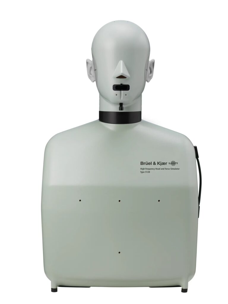
In industries where audio quality and acoustic accuracy can define a product’s success, the Head and Torso Simulator (HATS) is an indispensable tool. By replicating the acoustic properties of an average human head and torso, these manikins allow engineers to gather realistic data for telecommunications, automotive design, audiometry, and advanced research.
However, a HATS system is only as reliable as its calibration. Because these instruments are used in precision applications where measurement integrity is essential, understanding how they are calibrated is just as important as the calibration itself.
Component vs. Full-System Calibration
Traditionally, calibrating an acoustic manikin often meant disassembling the unit. Technicians would remove the individual ear simulators, microphones, and preamplifiers to test them independently in a laboratory setting.
While component calibration ensures that each separate part meets its specific tolerances, it introduces a critical blind spot: it fails to account for how the components interact as a unified system.
When a HATS is used in the field, sound waves interact with the physical structure of the head, the pinnae of the ears, and the contours of the torso. This interaction alters the acoustic response, a phenomenon known as the head-related transfer function (HRTF). Disassembly bypasses these geometric and acoustic influences.
The Free-Field Advantage
To capture the true performance of a HATS, it must be calibrated exactly as it is intended to be used: as a complete, fully assembled unit. This is achieved through free-field calibration.
Free-field calibration takes place inside an anechoic room, a specialised environment designed to completely absorb sound reflections and isolate the equipment from external noise.
The Process: The complete HATS system is placed in the anechoic chamber. Controlled acoustic signals are generated from precise angles, allowing technicians to measure the response of the entire system simultaneously.
The Benefit: This method accounts for the acoustic reflections, diffractions, and shielding caused by the physical shape of the manikin itself. It ensures that the microphones inside the ears are recording exactly what they would experience in a real-world testing scenario.
By choosing full-system free-field calibration over component breakdown, labs eliminate the risk of reassembly errors and gain a much higher level of confidence in their day-to-day measurement integrity.
Supported Industry Standards
At Campbell Associates, we provide UKAS-accredited free-field calibration for complete HATS systems within our custom-built anechoic room. Our facility is equipped to handle the industry’s most widely used precision acoustic manikins, ensuring your hardware remains compliant with international standards.
We regularly calibrate market-leading models, including:
Brüel & Kjær: Model 4128 Head and Torso Simulator
GRAS: KEMAR 45BB and 45BC Acoustic Manikins
Maintaining the accuracy of your simulator shouldn’t require compromising its structural integrity. By utilising full-system testing, you ensure that your data remains seamless, traceable, and perfectly reflective of human hearing.
Dealing with False Positives & How Weather Sensors Improve Noise/Dust Data Accuracy
News
Modern construction and industrial sites rely heavily on noise and dust monitoring systems to stay compliant, protect nearby communities, and maintain safe working conditions. However, one of the biggest challenges in environmental monitoring is dealing with false positives – situations where alarms or exceedances are triggered by external environmental conditions rather than actual site activity.
This is where integrated weather sensors play a major role in improving monitoring accuracy.
Weather data such as wind direction, wind speed, gusts, temperature, humidity, and rainfall provides important context to both noise and dust readings. For example, strong winds can carry dust from neighbouring areas onto a site, causing elevated particulate readings that may not be directly linked to on-site operations. By analysing wind direction and speed alongside dust data, environmental teams can quickly identify whether emissions are site-generated or coming from external sources.
Wind gust monitoring is equally important. Sudden gusts can create short-term spikes in airborne dust, especially during dry weather conditions. During prolonged dry periods, ground surfaces become loose and dusty, meaning even light vehicle movement or excavation work can produce significantly higher dust levels. Without weather data, these temporary increases could easily be misinterpreted as compliance failures.
Noise monitoring also benefits from weather integration. Wind can affect how sound travels, sometimes amplifying noise levels at monitoring locations. Gusty conditions may also interfere with microphones, creating inaccurate readings if weather protection and correction factors are not considered.
By combining environmental monitoring with real-time weather sensors such as our WeatherSens & WindSens monitors, operators gain a far clearer understanding of what is actually happening on-site. This helps reduce unnecessary investigations, improves reporting accuracy, and provides stronger evidence when responding to complaints or regulatory enquiries.
The Silent Friction of Net Zero: Managing Heat Pump Noise Nuisance
Environmental Health
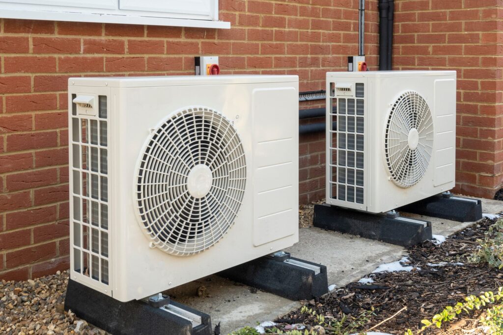
As the UK government accelerates its drive toward net zero emissions, the familiar hum of the gas boiler is rapidly being replaced by the whir of the air source heat pump (ASHP). Once a niche technology, heat pumps are fast becoming standard features across UK housing, particularly in modern new-build developments.
Yet, as these eco-friendly units multiply, local authority Environmental Health departments are finding themselves refereeing a new breed of neighbourly friction.
For the first time, the Chartered Institute of Environmental Health (CIEH) officially began tracking heat pump complaints as an independent category. Their data revealed that UK local authorities received 103 formal noise complaints over the 12-month period spanning 1 October 2024 to 30 September 2025. While 103 complaints represent just a tiny fraction of the hundreds of thousands of noise nuisances handled by councils every year, the figure marks the beginning of a distinct, upward trend.
On paper, the UK has strict safeguards to prevent heat pumps from becoming a acoustic menace. Under Permitted Development rules, a heat pump installation is only exempt from full planning permission if its calculated sound level does not exceed 42 dB at the position of the nearest neighbour’s window.
To put that in perspective, 42 dB is roughly equivalent to a quiet library or a gentle hum of a household refrigerator.
If the technology is legally mandated to be that quiet, the unit itself is rarely the problem. Instead, the friction arises because standard decibel testing measures overall sound pressure (dB(A)), which mimics human hearing by heavily filtering out very low pitches. What a standard sound test deems acceptable can feel entirely different to a neighbour trying to sleep on the other side of a party wall.
The true culprits behind council complaints usually boil down to two distinct acoustic phenomena: tonal noise and structural vibration.
The Low-Frequency Hum (Tonal Noise)
Unlike the random, rushing sound of wind or rain, a heat pump’s compressor and large fan blades emit what acoustics experts call tonal noise. This is a steady, continuous drone that typically oscillates at a low frequency between 50 Hz and 60 Hz.
Low-frequency sounds possess immense physical power. While high-pitched noises (like a television or a conversation) are easily deflected by standard brickwork and double-glazed windows, low-frequency waves pass right through them. The glass in a neighbour’s window can begin to resonate in sympathy with the 50 Hz drone, effectively transmitting a dull, bass-heavy hum straight into their bedroom.
Structure-Borne Vibration
Perhaps the most avoidable -yet most common cause of complaints is poor installation practice. A heat pump is a heavy piece of machinery containing a powerful, spinning motor. If an installer bolts the unit directly onto a residential brick wall, a timber-framed extension, or a flat roof without the correct mitigation, the entire structure suffers.
Without thick, high-quality rubber anti-vibration mounts or dedicated ground-mounted concrete plinths, the mechanical energy transfers directly into the building’s fabric. The walls of the property essentially act like a giant loudspeaker cone, amplifying the physical movement of the pump. Inside the house, this doesn’t sound like air; it manifests as an incredibly irritating, chest-thumping vibration that can be felt as much as it is heard.
For local authorities, resolving these disputes is a delicate balancing act. If a council investigation determines that a heat pump is causing a statutory nuisance under the Environmental Protection Act 1990, they are legally obligated to intervene.
Crucially, statutory nuisance looks at the real-world impact on a resident’s well-being, meaning a heat pump can be found at fault even if it technically passed the 42 dB planning assessment upon installation. When a nuisance is confirmed, councils can issue a legally binding Abatement Notice. This forces the homeowner to take immediate, often expensive corrective action—whether that means constructing specialized acoustic fencing, retrofitting heavy-duty dampening feet, or paying thousands to relocate the entire unit to the other side of the property.
As the UK marches steadily toward its net zero targets, the CIEH data serves as an early warning system. Achieving a green transition requires more than just swapping out old machinery; it demands rigorous installation standards, careful spatial design, and an understanding that keeping the planet warm shouldn’t come at the cost of the neighbourhood’s peace and quiet.
In the planning stages, developers and acoustic consultants can lean on noise prediction software like CadnaA to anticipate and mitigate acoustic risks, saving developers and buyers from future legal headaches.
But for Environmental Health Officers investigating complaints under the Environmental Protection Act 1990, resolving noise issues is rarely straightforward. EHOs must first map out the local environment’s natural baseline sound levels before measuring the heat pump at its loudest—usually during the depths of winter. Conducting these precise evaluations demands a reliable, fully calibrated Class 1 sound level meter, such as the Larson Davis 821. Furthermore, if a dispute requires long-term tracking, officers may need to deploy unattended meters for several days to capture a truly accurate baseline. The Larson Davies 821 with solar panel has proven to be reliable and accurate in these scenarios.
Automating Your Weekly Environmental Reports: How to Save 4 Hours of Admin
Tips & Tricks
For most construction companies, environmental monitoring isn’t optional, it’s a requirement driven by local council conditions, planning approvals, and Section 61 agreements.
We understand that producing weekly environmental reports for noise, dust, and vibration monitoring can be very time-consuming. Even when the data is readily available from the monitors, the process of downloading, organising, analysing, and formatting it into a compliant report often takes longer than expected, especially when managing multiple sites or strict council requirements.
To reduce this administrative burden, we offer automated reporting. The Sonitus Cloud takes logged data from the monitors on site and automatically generates a structured report.
What will be included in my report?
Information on the monitors including model, serial number, location and calibration dates.
Hourly averages and daily averages for the noise and dust monitors.
Daily maximums for the vibration monitors.
Any exceedances/breaches for all monitors.
When are the reports sent?
Weekly reports will be generated on Monday mornings. Monthly reports will be generated on the first day of the month. The reports will be sent to users selected on the project by email. Historical reports are also available for download in the Reports tab on the cloud.
Can I generate more of a custom report?
Yes – please watch our loom video for instructions on how to do this.
Unattended Environmental Noise Monitoring Without Mains Power: Larson Davis SoundExpert 821
Noise
Environmental noise impact assessments frequently demand long-term, unattended monitoring in remote locations completely devoid of grid power. Whether you are conducting baseline surveys for rural wind farms, managing Section 61 compliance on infrastructure projects, or tracking long-term construction noise, data continuity is paramount.
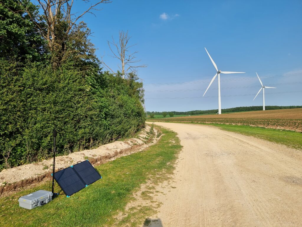
The Larson Davis SoundExpert 821 Environmental Kit, supplied in the UK by Campbell Associates, provides a highly dependable solution. When integrated with a dedicated solar panel kit, it offers UK acoustic consultants a rugged, off-grid setup that eliminates the logistical headache and risk of frequent battery swaps.
Solar-Powered Reliability: Proven in the UK Climate
A common concern with solar-powered instrumentation in the UK is the lack of reliable daylight, particularly during winter or in northern latitudes. The SoundExpert 821 addresses this through exceptionally low power consumption.
The system’s real-world capability was demonstrated during a 60-day deployment in the Scottish Highlands. Operating solely on solar power through challenging, overcast conditions and limited daylight hours, the system delivered 100% data continuity. Upon collection, the internal battery remained fully charged. For consultants, this level of efficiency means fewer site visits, reduced travel costs, and zero risk of data gaps.
Key Features:
Ultra-Portable Solar: Lightweight, foldable panel that a single person can easily carry and set up.
All-Weather Protection: Rugged kit designed to shield components from both heavy rain and insects.
Extreme-Cold Battery: High-performance battery engineered to operate in freezing temperatures down to -30°C.
High-Frequency Logging: Captures data at short logging intervals for precise tracking.
Comprehensive Data Types: Records audio, frequency data, and analysis results.
Flexible Downloading: Easily export your data via SD card, USB, or Bluetooth.
Dedicated Software: Seamless integration with the G4 LD Utility software for managing and analysing downloads.
Applications for UK Acoustic Consultants
With its robust weatherproof enclosure and autonomous power capabilities, the SoundExpert 821 kit is optimised for a variety of demanding applications:
Wind Farm & Renewable Energy Assessments: Continuous background noise logging in remote upland areas in line with ETSU-R-97 guidance.
Construction & Infrastructure Monitoring: Long-term boundary monitoring for major civils, highways, and rail projects operating under BS 5228.
Remote Baseline Surveys: Planning application data collection in rural areas where mains power is inaccessible.
Industrial Noise Impact Assessments: Long-term monitoring for BS 4142 assessments where an extended reference period is required.
Class 1 Accuracy at a Competitive Price Point
Maintaining a fleet of sound level meters can be capital-intensive. At approximately £4,600, the Larson Davis SoundExpert 821 Environmental Kit represents one of the most cost-effective Class 1 (Type 1) outdoor monitoring systems on the UK market.
It strips away the unnecessary complexity and premium price tag of permanent, fixed-installation systems while strictly maintaining the measurement accuracy required for legally defensible environmental reporting and planning submissions.
To discuss hire options or purchase specifications, contact the team at Campbell Associates.
Our director Ian Campbell MSc, FIOA has spent his career working in the acoustic industry and has written a full technical report on reviving the sound level indicator. A shortened version can be read below, see the full report at the bottom on this post.
While modern standards like BS 61672 introduced high-precision engineering and precision instruments in 2002 , the older Grade 3 Sound Level Indicators (SLIs) are far from extinct. In fact, the market is currently flooded with models ranging from under £100 to over £500. However, because these devices have been absent from official quality control standards for over 25 years, users must be diligent about the uncertainty of the results they provide.
The Precision Gap
The primary risk with SLIs is specification creep, where manufacturers make vague claims about conforming to British Standards that can easily be misunderstood by beginners. Unlike professional Sound Level Meters (SLMs), SLIs rarely come with a sound calibrator. Without this reference tool to set the device to the international standard of 94 dB, any natural drift caused by the environment or time goes completely unnoticed.
Understanding High-Frequency Errors
A major technical hurdle involves how sound interacts with the device itself. To ensure a flat response in an open free-field, microphone designers actually engineer the microphone’s internal pressure response to fall off at higher frequencies. While this works perfectly in open air, it causes the SLI to significantly under-report decibel levels when checked with a standard closed-cavity calibrator.
Furthermore, the physical body of the SLI reflects sound waves, creating interference that further distorts measurements. While professional SLM manufacturers provide complex correction tables to account for these reflections, such data is rarely available for budget SLIs.
A Sustainable Calibration Path
To bridge this gap economically, owners should consider an initial free-field calibration in an anechoic chamber. This one-time test captures the combined effects of the microphone and case reflections, providing the necessary data to calculate corrections. Once this baseline is established, future re-calibrations can be performed using lower-cost pressure methods while maintaining technical integrity.
Calibration Phase
Estimated Cost
Technical Benefit
Initial Free-Field
£225
Documents exact case and frequency corrections.
Annual Pressure
£140
Ensures alignment to the international dB scale.
Ultimately, while SLIs lack the stability and dynamic range of professional meters, they remain a valuable entry point for noise measurement if their limitations are managed through proper, recorded calibration.
Why mounting position matters for weather stations
News
Accurate wind measurement requires what standards describe as free field conditions. In simple terms, this means the sensor must be positioned where airflow is not influenced by nearby obstructions.
International guidance such as ISO 16622 and WMO meteorological siting recommendations state that wind sensors should be installed well clear of buildings, structures and terrain features that distort airflow. A common rule of thumb is that a sensor should be positioned at a distance of at least 10 times the height of nearby obstructions, or mounted at least twice the height of the nearest structure to reduce interference effects. On construction sites, achieving true free field conditions is extremely challenging.
Why is it so difficult?
Wind does not simply pass around buildings unchanged. When wind strikes a building or structure:
Its direction is altered
Turbulence is created
Accelerated flow zones can form around edges
Wind shadow areas can develop behind structures
If a wind monitor is installed close to, between, or downwind of buildings or scaffolding, the readings will reflect localised airflow, not true background wind speed and direction. This does not mean the data is useless, but it does mean the data must be understood in context.
What About Crane Wind Monitoring?
For crane safety applications, wind sensors are typically installed at the very top of the crane. In many cases this provides a reasonably exposed location, which is beneficial.
However, even crane mounted sensors can be affected by:
Nearby high rise structures
Tower crane masts
Adjacent buildings under construction
Complex urban airflow patterns
So while elevated mounting improves accuracy, it does not automatically guarantee true meteorological conditions.
Does This Make Wind Monitoring on Construction Sites Pointless?
No. It simply changes how the data should be interpreted. In environmental monitoring, the purpose is often not to measure absolute meteorological wind speed, but to understand:
Wind direction trends
Site influence
Dust transport patterns
Relative changes over time
For example, if you measured dust at two locations 100 metres apart along a street, and installed three wind sensors across the site boundary, you would expect to see:
A consistent wind pattern across sensors
A directional trend
Correlation between higher dust readings and downwind locations
If wind sensors show a stable direction from west to east, and dust levels are low on the west side and elevated on the east side, this provides strong evidence of transport across the site. In this context, consistency and correlation are often more important than perfect free field meteorological accuracy.
How Reliable Are Weather Sensors on Construction Sites?
They are very useful, but they should not be relied upon in isolation.
Best practice is to:
Combine wind data with dust or noise monitoring
Understand local obstructions
Record mounting height and proximity to structures
Maintain consistent siting throughout the project
The key is transparency. If the siting is documented and understood, the data remains defensible.
What Sensor Could Be Used in Optimal Conditions?
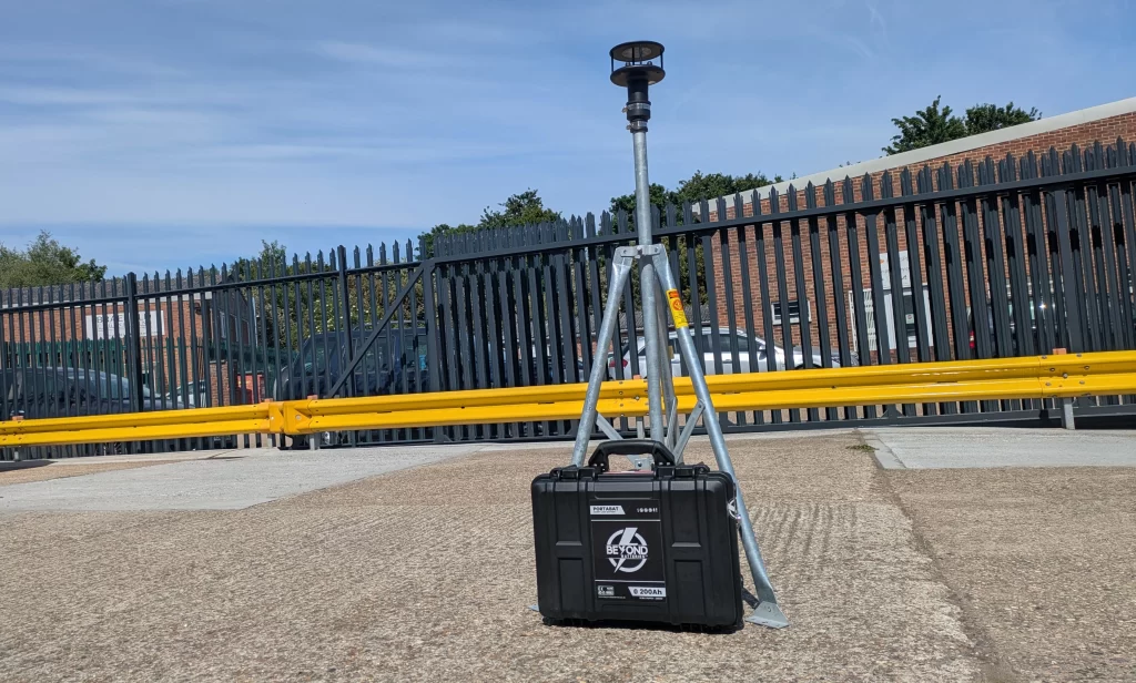
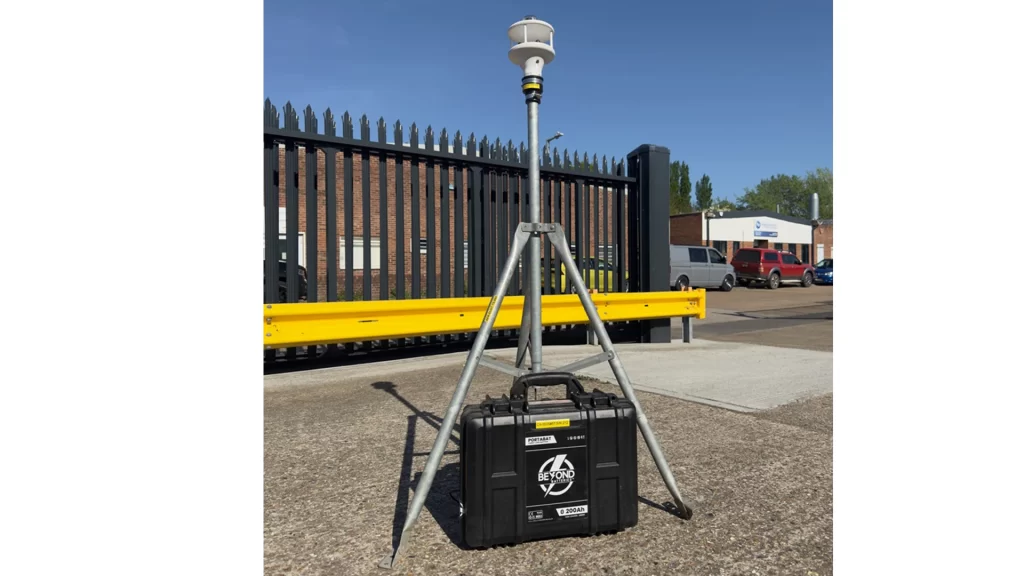
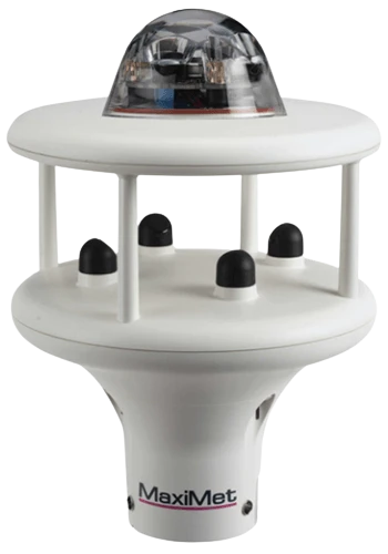
The MAX600 is an example of a compact weather station suitable for construction and environmental applications. It measures:
Wind speed
Wind direction
Temperature
Relative humidity
Ultrasonic wind sensors, such as those used in the MAX600, operate without moving parts. They transmit ultrasonic pulses between transducers and calculate wind speed and direction based on the time it takes for sound waves to travel between them. This provides:
Fast response
Low maintenance
Improved durability in harsh environments
Installation Best Practice
Once installed, the sensor should be:
Clear of nearby structures
Away from scaffolding
Not mounted directly against scaffold tubes
Positioned to avoid wind tunnel effects
Scaffolding in particular can significantly distort airflow. Tubes and platforms can create acceleration zones and turbulence, producing readings that reflect structural interference rather than true site wind.
Ideally, the monitor should be mounted:
Above roof level
With clear 360° exposure
Several metres above the roof surface
Away from roof edges
A dedicated rooftop mast or tripod is often preferable to mounting directly onto scaffold.
Final Thoughts
Perfect meteorological siting is rarely achievable on active construction sites. However, with good planning, sensible positioning and proper data interpretation, weather sensors remain a valuable and defensible tool for environmental and safety monitoring. The key is not perfection. It is understanding the limitations and designing the monitoring strategy accordingly.
Are All MCERTS dust monitors suitable for construction projects?
Air Quality & Dust
MCERTS-certified indicative dust monitors are widely specified for construction projects across the UK. However, are all MCERTS monitors truly suitable for construction applications?
The MCERTS indicative certification is primarily achieved through comparative measurements against reference-grade instruments in background (ambient) locations. To gain certification, a sample of instruments must demonstrate good long-term correlation with the reference method.
While this approach is appropriate for ambient community air quality monitoring, it does not necessarily mean a monitor is suitable for construction environments. There are several important differences to consider:
1. Averaging Periods
MCERTS indicative assessments are based on 24-hour average measurements. This works well for community air quality monitoring, where daily mean values are the primary concern.
Construction projects, however, typically operate over a working day of around 10 hours, with dust limits often defined over hourly or 15 minute periods. Monitoring systems therefore need to:
Measure accurately over short averaging periods
Identify dust events in real time
Trigger immediate alerts when limits are exceeded
A monitor optimised for 24-hour averages may not provide the responsiveness required on a live construction site.
2. Concentration Ranges
MCERTS comparative testing is conducted at ambient locations where particulate concentrations are relatively low – typically around 40 µg/m³.
Construction sites, by contrast, can generate significantly higher dust levels, often 150 µg/m³ or more. Dust monitors used on construction projects must therefore maintain accuracy across a much wider and higher concentration range than is typically encountered in ambient environments.
3. Measurement of PM₁₀
Although all MCERTS indicative dust monitors report PM₁₀, not all of them directly measure it.
Some instruments measure PM₂.₅ and apply a fixed conversion factor to estimate PM₁₀. In ambient environments, this can produce good correlation because PM₂.₅ and PM₁₀ levels often track closely together.
On construction sites, however, dust sources are very different. Coarser particles are more prevalent, and PM₁₀ does not necessarily follow PM₂.₅ in the same way. For construction applications, it is important that the optical sensor directly measures PM₁₀ rather than inferring it.
Many MCERTS indicative monitors are not fitted with heated inlets.
Heated inlets are used to dry the sample air and remove fog and mist droplets, which would otherwise be detected as particulate matter. In construction monitoring, particularly where reporting periods are short fog or mist can generate false dust events if the sample air is not properly conditioned.
Choosing the Right Monitor
MCERTS certification ensures environmental data is accurate and reliable, but certification alone does not guarantee suitability for every application.
When selecting a dust monitor for construction, it is essential to consider:
Short-term averaging capability
Performance at higher concentration ranges
True PM₁₀ measurement
Effective inlet conditioning
If you are unsure which type of dust monitor is most appropriate for your project, please contact the team at Campbell Associates for advice.
MCERTS is the Environment Agency certification scheme designed to ensure environmental monitoring equipment meets defined standards of accuracy and reliability.
Why monitoring dust at night is essential on construction sites in the UK
Air Quality & Dust
Construction activity may slow or stop overnight, but dust emissions do not simply switch off. In fact, certain night-time conditions can lead to elevated readings, making continuous monitoring just as important after dark as it is during the working day.
Understanding why this happens and how to manage it is key to protecting public health, maintaining compliance, and safeguarding a project’s reputation.
Why Dust Levels Can Rise at Night
1. Increased Wind Speeds in the Evening
It is not uncommon for wind speeds to increase after sunset. One important atmospheric phenomenon behind this is the nocturnal low level jet.
As the ground cools rapidly at night, the air close to the surface becomes stable and calm. This layer effectively decouples from stronger winds higher up. Without surface friction to slow them down, these higher altitude winds can accelerate and move closer to ground level.
When wind speed increases:
Dry dust piles are more easily disturbed
Exposed surfaces release fine particles
Previously deposited dust can be re suspended
Even if no active work is taking place, environmental conditions alone can drive emissions.
2. Drying of Surfaces
Evaporation can continue into the evening, particularly after a warm day. When combined with higher wind speeds, exposed materials dry out more quickly. Drier surfaces mean finer particles are more easily lifted into the air.
Without proper controls in place before leaving site, dust can become airborne overnight.
3. Early Morning Fog and Optical Monitors
In the early hours, fog events are common. Optical particle counters may detect water droplets because they are similar in size to dust particles. This can lead to elevated readings that do not represent true particulate pollution.
Water particles are inherently not a health risk in the same way as mineral dust, but they can affect data accuracy.
Modern monitoring technologies address this in two main ways:
Predictive algorithms that distinguish likely fog events
Heated inlets that dry incoming air, removing water droplets before measurement
By physically resolving the issue through air drying, readings more accurately reflect real dust concentrations.
Why Night Time Dust Still Matters
Airborne particles such as PM10 and smaller are hazardous to health. Fine particulate pollution contributes to respiratory and cardiovascular disease and is linked to over one hundred thousand early deaths each year in the United Kingdom.
Children and infants are particularly vulnerable.
The responsibility to control nuisance dust and protect health does not end when workers leave the site. Emissions continue to have an environmental impact throughout the night, affecting nearby residents and sensitive receptors.
Regulatory limits are often based on short averaging periods such as fifteen minutes or one hour. However, these limits do not negate the need for continuous oversight. A sustained moderate elevation overnight can still have environmental and reputational consequences.
Practical Controls Before Leaving Site
Effective dust management overnight starts with preparation. Site managers should ensure that appropriate controls are in place before work finishes for the day.
These include:
Covering dust piles
Wetting down exposed materials
Closing doors to contain internal areas
Installing barriers and hoarding to limit dispersion
Securing stockpiles against wind disturbance
Proactive management significantly reduces the risk of overnight exceedances.
The Value of Continuous Monitoring
Continuous dust monitoring provides visibility when the site is unattended. It allows managers to:
Identify patterns linked to wind speed and weather
Detect elevated night time concentrations
Assess the effectiveness of control measures
Plan improvements for future shifts
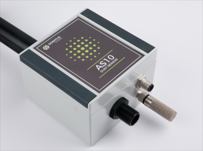
Systems such as the SiteSens and the DustSens DM30 from Campbell Associates enable reliable long term monitoring, including mitigation of fog related measurement issues through advanced technology.
Sonitus Systems SiteSens DustSens Site Engineer Weather Wind Tripod Environmental Outdoor
Where immediate night time alerts may not be practical, alternative strategies can be implemented. For example, lower thresholds can be applied over longer averaging periods to detect sustained elevated levels overnight. Alerts can then be delivered at the end of the monitoring window, allowing action to be taken the following morning.
Protecting Health, Environment and Reputation
Construction sites operate within communities. The duty of care to minimise nuisance and protect health continues twenty four hours a day.
Night time dust monitoring is not simply a regulatory exercise. It is a proactive approach to:
Safeguarding public health
Reducing environmental impact
Demonstrating responsible site management
Avoiding complaints and enforcement action
By combining robust controls with continuous monitoring and modern measurement technology, construction sites can ensure that dust is managed effectively at all hours.
Because dust does not stop when work does, neither should monitoring.
According to the World Health Organisation’s (WHO) Global Air Quality Guidelines:
Annual average for PM10: 15 micrograms per cubic metre (µg/m³)
24-hour average for PM10: 45 µg/m³
These are the guideline levels recommended to protect human health; they are not legally binding limits but serve as health-based benchmarks for air quality policy and planning.
The Institute of Air Quality Management (IAQM) guidance for construction and demolition sites does not prescribe fixed statutory UK air quality limit values for PM10 like those set for general ambient air (eg World Health Organisation or national objectives). Instead, it focuses on best practice dust risk assessment, monitoring and action trigger levels to manage dust emissions from sites.
Action trigger levels / monitoring guidance
For sites assessed as medium or high risk of dust impact, the IAQM’s monitoring guidance (2018 document Guidance on Air Quality Monitoring in the Vicinity of Demolition and Construction Sites) recommends real time PM10 monitoring with site-specific action levels or, where a generic level is used, a trigger level of 190 µg/m³ (one hour mean) to prompt investigation and corrective action. Monitoring should be proportional to the assessed risk and agreed with the local authority.
Read more about IAQM’s position on low cost dust sensors here.
Mastering Section 61: The ultimate guide to environmental monitoring and compliance
News
For construction and demolition firms in the UK, navigating the Control of Pollution Act 1974 is a critical component of project delivery. Specifically, securing a Section 61 consent is the gold standard for proactive site management. It not only protects your project from the risk of a Section 60 stop-work notice but also demonstrates your commitment to Best Practicable Means (BPM) in mitigating noise, vibration, and dust.
At Campbell Associates, we provide more than just equipment; we provide a full-spectrum partnership to guide you through the Section 61 application process, from baseline surveys to automated compliance reporting.
What is a Section 61 Application and Why is it Essential?
A Section 61 application is a formal request for prior consent from a Local Authority regarding the noise and vibration impact of your planned works. By securing this agreement before you break ground, you achieve:
Legal Protection: Compliance with a Section 61 agreement prevents the council from serving a Section 80 abatement notice or a Section 60 notice, which can impose strict working hours or halt production.
Community Trust: Providing a clear Dust Management Plan (DMP) and noise mitigation strategy reduces community complaints and enhances your brand reputation.
Operational Certainty: You establish agreed-upon threshold limits and working hours, allowing for accurate project scheduling and budgeting.
How Campbell Associates Supports Your Section 61 Journey
We help you meet the rigorous requirements of BS 5228 (Noise and Vibration Control on Construction and Open Sites) and IAQM (Institute of Air Quality Management) guidance through a three-stage approach:
1. Pre-Construction: Baseline Surveys and Prediction
Before work begins, you must establish the existing ambient levels of the area. We provide Class 1 Sound Level Meters and Vibration Monitors to conduct accurate baseline surveys.
Acoustic Prediction: We offer CadnaA noise prediction software to help you model the impact of your plant and machinery, a vital part of your Section 61 submission.
2. Construction Phase: Real-Time Monitoring & NVD Strategy
Once the project is live, our NVD (Noise, Vibration, and Dust) monitors provide the 24/7 data required to prove you are working within your agreed limits.
Noise Monitoring: Our NoiseSens and SiteSens systems offer remote access and audio triggers to identify the source of any noise breach.
Vibration Monitoring: Using the Syscom Rock we measure Peak Particle Velocity (PPV) to protect sensitive structures and satisfy BS 7385-2 requirements.
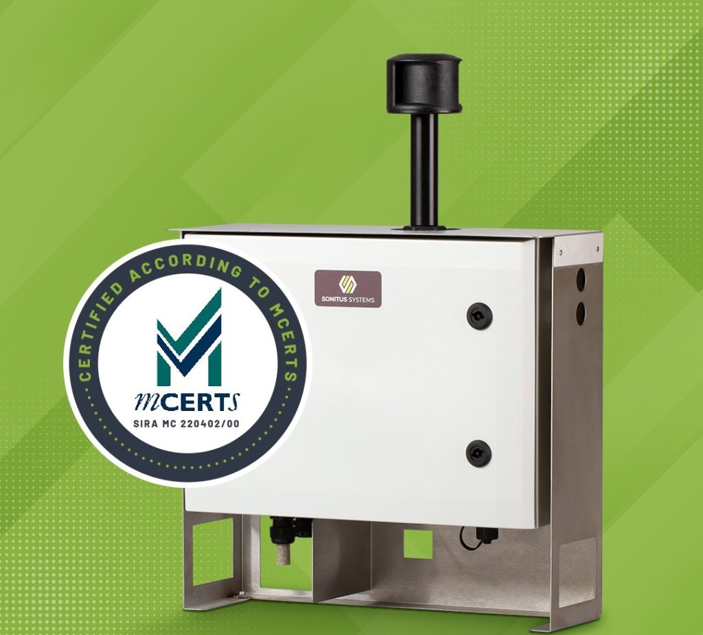
Dust Monitoring: Our DustSens systems are MCERTS certified, utilising heated inlets to ensure accurate PM10 and PM2.5 readings, even in the UK’s high humidity.
3. Compliance & Reporting: The Sonitus Cloud
The key to a successful Section 61 is the audit trail. All Campbell Associates monitors feed data into the Sonitus Cloud, a centralised portal that:
Automates Reporting: Generate weekly or monthly compliance reports to send directly to Environmental Health Officers (EHOs).
Instant Alerts: Receive SMS and email notifications the moment a threshold is approached, allowing for immediate on-site mitigation.
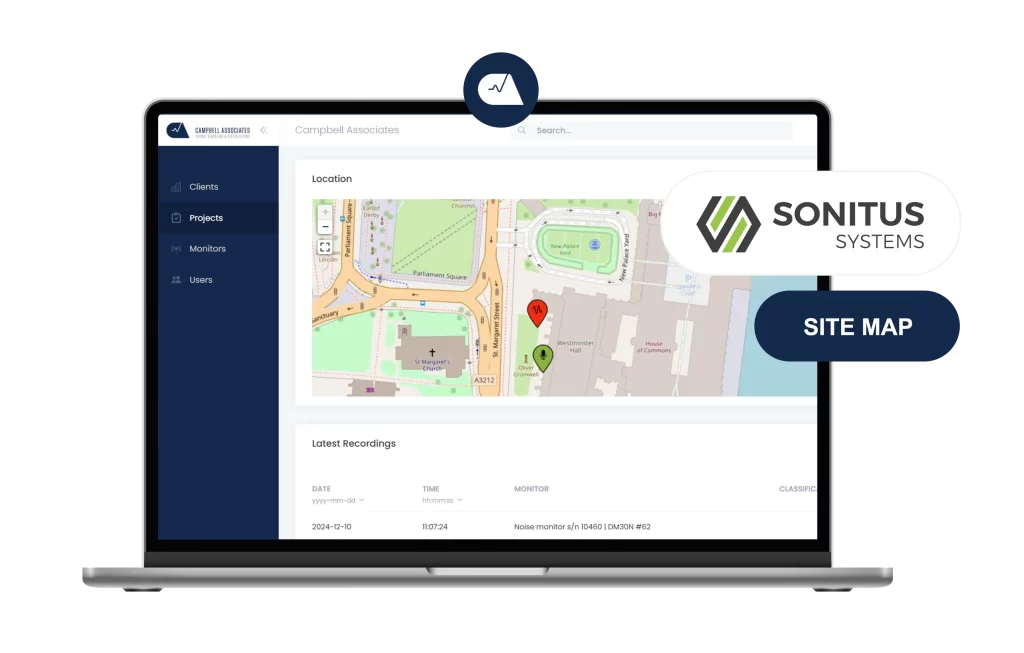
Sonitus Cloud Map
Optimising Your Site with Integrated Environmental Monitoring
Monitoring Type
Primary Regulation/Standard
Equipment Solution
Noise
CoPA 1974 / BS 5228-1
SiteSens / NoiseSens
Vibration
BS 5228-2 / BS 7385-2
Syscom Rock / AvaTrace
Dust (Air Quality)
Environment Act / IAQM
DustSens (MCERTS)
Don’t Risk Your Project’s Timeline
A failed Section 61 submission or a single noise complaint can cost thousands in delays. By partnering with Campbell Associates, you ensure your site is equipped with the UK’s most reliable, MCERTS-certified and Class 1 monitoring technology.
Would you like our team to review your upcoming project requirements and recommend a bespoke monitoring package for your Section 61 application?
To provide the best experiences, we use technologies like cookies to store and/or access device information. Consenting to these technologies will allow us to process data such as browsing behavior or unique IDs on this site. Not consenting or withdrawing consent, may adversely affect certain features and functions.
Functional
Always active
The technical storage or access is strictly necessary for the legitimate purpose of enabling the use of a specific service explicitly requested by the subscriber or user, or for the sole purpose of carrying out the transmission of a communication over an electronic communications network.
Preferences
The technical storage or access is necessary for the legitimate purpose of storing preferences that are not requested by the subscriber or user.
Statistics
The technical storage or access that is used exclusively for statistical purposes.The technical storage or access that is used exclusively for anonymous statistical purposes. Without a subpoena, voluntary compliance on the part of your Internet Service Provider, or additional records from a third party, information stored or retrieved for this purpose alone cannot usually be used to identify you.
Marketing
The technical storage or access is required to create user profiles to send advertising, or to track the user on a website or across several websites for similar marketing purposes.